

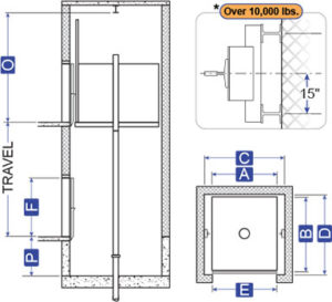
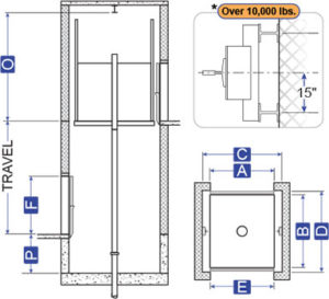
A = Platform Width
B = Platform Depth
C = Hoistway Width
D = Hoistway Depth
E = Clear Door Width
F = Clear Door Height
O = Overhead
P = Pit Depth
R = Door Clearance
R = 5″ for Regular Type Doors
R = 7″ for Pass Type Doors

Download Available Information
Contact an Elevator Package Representative to place an order
Application Summary
This is the traditional design used for decades. lt utilizes a hydraulic jack installed in the ground. The jack is located directly under the car, near the center of the platform.
Advantages
- Usually the lowest material cost application.
- Accommodates front and rear openings in any configuration.
- No extensive pit or overhead is required.
- Available for both low and high capacity cars.
- Of all the application types, this equipment package is the easiest to install.
Code year adoptions and local code variations may affect the hoistway size. Verify all dimensions with MEI prior to construction.
ENGINEERED TO ORDER – Contact MEI For Sizes or Capacities Outside Listed Ranges
Specifications
Freight Elevators – Standard Specifications
Capacity (lbs)
Platform
A x B
A x B
Hoistway With Power Regular Doors
C x D
C x D
Hoistway With Power Pass Doors
C x D
C x D
Pit Depth
P
P
Front/Rear
Clear Inside With Single Section Gate WxD
Clear Inside With Two Section Gate WxD
Door Width & Height
E x F
E x F
Elevation & Plan View Drawings
4000 Lbs
7′ -0″ x 8′ -0″
8′ -8″ x 8′ -8″
8’-8” x 8’-9 3⁄4”
4′ -6″
F
6′ -8″ x 7′ -7″
6′ -8″ x
7′ -4 1/2“
7′ -4 1/2“
6′ -8″ x 8′ -0″
4000 Lbs
7′ -0″ x 8′ -0″
8′ -8″ x 8′ -10″
8’-8” x 9’-1 1⁄2”
4′ -6″
F/R
6′ -8″ x 7′ -6″
6′ -8″ x 7′ -1“
6′ -8″ x 8′ -0″
5000 Lbs
8′ -0″ x 9′ -0″
9′ -10″ x 9′ -8″
9’-10” x 9’-9 3⁄4”
4′ -6″
F
7′ -8″ x 8′ -7″
7′ -8″ x
8′ -4 1/2“
8′ -4 1/2“
7′ -8″ x 8′ -0″
5000 Lbs
8′ -0″ x 9′ -0″
9′ -10″ x 9′ -10″
9’-10” x 10’-1 1⁄2”
4′ -6″
F/R
7′ -8″ x 8′ -6″
7′ -8″ x 8′ -1″
7′ -8″ x 8′ -0″
6000 Lbs
10′ -4″ x 10′ -0″
12’-2” x 10’-8”
12′ -2″ x 10′ -9 3/4″
4′ -6″
F
10′ -0″ x 9′ -7″
10′ -0″ x
9′ -4 1/2“
9′ -4 1/2“
10′ -0″ x 8′ -0″
6000 Lbs
10′ -4″ x 10′ -0″
12′ -2″ x 10′ -10″
12’-2” x 11’-1 1⁄2”
4′ -6″
F/R
10’-0” x 9’-6”
10′ -0″ x 9′ -1“
10′ -0″ x 8′ -0″
8000 Lbs
10′ -4″ x 12′ -0″
12′ -4″ x 12′ -8″
12’-4” x 12’-9 3⁄4”
4′ -6″
F
10′ -0″ x 11′ -7″
10′ -0″ x
11′ -4 1/2“
11′ -4 1/2“
10′ -0″ x 8′ -0″
8000 Lbs
10′ -4″ x 12′ -0″
12′ -4″ x 12′ -10″
12’-4” x 13’-1 1⁄2”
4′ -6″
F/R
10′ -0″ x 11′ -6″
10′ -0″ x 11′ -1“
10′ -0″ x 8′ -0″
10000 Lbs
10′ -4″ x 14′ -0″
12′ -4″ x 14′ -8″
12’-4” x 14’-9 3⁄4”
4′ -6″
F
10′ -0″ x 13′ -7″
10′ -0″ x
13′ -4 1/2“
13′ -4 1/2“
10′ -0″ x 8′ -0″
10000 Lbs
10′ -4″ x 14′ -0″
12′ -4″ x 14′ -10″
12’-4” x 15’-1 1⁄2”
4′ -6″
F/R
10′ -0″ x 13′ -6″
10′ -0″ x 13′ -1“
10′ -0″ x 8′ -0″
12000 Lbs
12′ -4″ x 12′ -0″
14′ -4″ x 12′ -8″
14’-4” x 12’-9 3⁄4”
4′ -6″
F
12′ -0″ x 11′ -7″
12′ -0″ x
11′ -4 1/2“
11′ -4 1/2“
12′ -0″ x 8′ -0″
12000 Lbs
12′ -4″ x 12′ -0″
14′ -4″ x 12′ -10″
14’-4” x 13’-1 1⁄2”
4′ -6″
F/R
12′ -0″ x 11′ -6″
12′ -0″ x 11′ -1“
12′ -0″ x 8′ -0″
15000 Lbs
12′ -4″ x 16′ -0″
14′ -4″ x 16′ -8″
14’-4” x 16’-9 3⁄4”
5′ -0″
F
12′ -0″ x 15′ -7″
12′ -0″ x
15′ -4 1/2“
15′ -4 1/2“
12′ -0″ x 8′ -0″
15000 Lbs
12′ -4″ x 16′ -0″
14′ -4″ x 16′ -10″
14’-4” x 17’-1 1⁄2”
5′ -0″
F/R
12′ -0″ x 15′ -6″
12′ -0″ x 15′ -1“
12′ -0″ x 8′ -0″
20000 Lbs
12′ -4″ x 20′ -0″
14′ -4″ x 20′ -8″
14’-4” x 20’-9 3⁄4”
5′ -0″
F
12′ -0″ x 19′ -7″
12′ -0″ x
19′ -4 1/2“
19′ -4 1/2“
12′ -0″ x 8′ -0″
20000 Lbs
12′ -4″ x 20′ -0″
14′ -4″ x 20′ -10″
14’-4” x 21’-1 1⁄2”
5′ -0″
F/R
12′ -0″ x 19′ -6″
12′ -0″ x 19′ -1“
12′ -0″ x 8′ -0″
25000 Lbs
14′ -4″ x 20′ -0″
16′ -4″ x 20′ -8″
16’-4” x 20’-9 3⁄4”
5′ -6″
F
14′ -0″ x
19′ -5 1/2“
19′ -5 1/2“
14′ -0″ x 19′ -3″
14′ -0″ x 8′ -0″
25000 Lbs
14′ -4″ x 20′ -0″
16′ -4″ x 20′ -10″
16’-4” x 21’-1 1⁄2”
5′ -6″
F/R
14′ -0″ x 19′ -3″
14′ -0″ x 18′ -10″
14′ -0″ x 8′ -0″
Automobile Lifts
Capacity (lbs)
Platform
A x B
A x B
Hoistway With Power Regular Doors
C x D
C x D
Hoistway With Power Pass Doors
C x D
C x D
Pit Depth
P
P
Front/Rear
Clear Inside With Single Section Gate
WxD
WxD
Clear Inside With Two Section Gate
WxD
WxD
Door Width & Height
E x F
E x F
Min. Overhead With One Section Gate
Max. Speed FPM
Elevation & Plan View Drawings
8000 Lbs
9′ -4″ x 21′ -8″
11′ -0″ x 22′ -4″
11’-0” x 22’6”
4′ -6″
F
9′ -0″ x 21′ -3″
9′ -0″ x
21′ -0 1/2“
21′ -0 1/2“
9′ -9″
14’-7”
150
8000 Lbs
9′ -4″ x 21′ -8″
11′ -0″ x 22′ -6″
11’-0” x 22’-10”
4′ -6″
F/R
9′ -0″ x 21′ -2″
9′ -0″ x 20′ -9″
9′ -9″
14’-7”
150
10000 Lbs
10′-4″ x 23′-0″
12′-0″ x 23′-8″
12’-0” x 23’-10”
4′ -6″
F
10′-0″ x 22′-7″
10′-0″ x 22′-4 1⁄2″
10’ x 9’
14’-7”
150
10000 Lbs
10′-4″ x 23′-0″
12′-0″ x 23′-10″
12’-0” x 24’-2”
4′ -6″
F/R
10′-0″ x 22′-6″
10′-0″ x 22′-1″
10’ x 9’
14’-7”
150
Freight Elevators – Standard Specifications
4000 Lbs
7′ -0″ x 8′ -0″
8′ -8″ x 8′ -8″
8’-8” x 8’-9 3⁄4”
4′ -6″
F
6′ -8″ x 7′ -7″
6′ -8″ x
7′ -4 1/2“
7′ -4 1/2“
6′ -8″ x 8′ -0″
4000 Lbs
7′ -0″ x 8′ -0″
8′ -8″ x 8′ -10″
8’-8” x 9’-1 1⁄2”
4′ -6″
F/R
6′ -8″ x 7′ -6″
6′ -8″ x 7′ -1“
6′ -8″ x 8′ -0″
5000 Lbs
8′ -0″ x 9′ -0″
9′ -10″ x 9′ -8″
9’-10” x 9’-9 3⁄4”
4′ -6″
F
7′ -8″ x 8′ -7″
7′ -8″ x
8′ -4 1/2“
8′ -4 1/2“
7′ -8″ x 8′ -0″
5000 Lbs
8′ -0″ x 9′ -0″
9′ -10″ x 9′ -10″
9’-10” x 10’-1 1⁄2”
4′ -6″
F/R
7′ -8″ x 8′ -6″
7′ -8″ x 8′ -1″
7′ -8″ x 8′ -0″
6000 Lbs
10′ -4″ x 10′ -0″
12’-2” x 10’-9 3⁄4”″
12′ -2″ x 10′ -10″
4′ -6″
F
10′ -0″ x 9′ -7″
10′ -0″ x
9′ -4 1/2“
9′ -4 1/2“
10′ -0″ x 8′ -0″
6000 Lbs
10′ -4″ x 10′ -0″
12′ -2″ x 10′ -10″
12’-2” x 11’-1 1⁄2”
4′ -6″
F/R
10’-0” x 9’-6”
10′ -0″ x 9′ -1“
10′ -0″ x 8′ -0″
8000 Lbs
10′ -4″ x 12′ -0″
12′ -4″ x 12′ -8″
12’-4” x 12’-9 3⁄4”
4′ -6″
F
10′ -0″ x 11′ -7″
10′ -0″ x
11′ -4 1/2“
11′ -4 1/2“
10′ -0″ x 8′ -0″
8000 Lbs
10′ -4″ x 12′ -0″
12′ -4″ x 12′ -10″
12’-4” x 13’-1 1⁄2”
4′ -6″
F/R
10′ -0″ x 11′ -6″
10′ -0″ x 11′ -1“
10′ -0″ x 8′ -0″
10000 Lbs
10′ -4″ x 14′ -0″
12′ -4″ x 14′ -8″
12’-4” x 14’-9 3⁄4”
4′ -6″
F
10′ -0″ x 13′ -7″
10′ -0″ x
13′ -4 1/2“
13′ -4 1/2“
10′ -0″ x 8′ -0″
10000 Lbs
10′ -4″ x 14′ -0″
12′ -4″ x 14′ -10″
12’-4” x 15’-1 1⁄2”
4′ -6″
F/R
10′ -0″ x 13′ -6″
10′ -0″ x 13′ -1“
10′ -0″ x 8′ -0″
12000 Lbs
12′ -4″ x 12′ -0″
14′ -4″ x 12′ -8″
14’-4” x 12’-9 3⁄4”
4′ -6″
F
12′ -0″ x 11′ -7″
12′ -0″ x
11′ -4 1/2“
11′ -4 1/2“
12′ -0″ x 8′ -0″
12000 Lbs
12′ -4″ x 12′ -0″
14′ -4″ x 12′ -10″
14’-4” x 13’-1 1⁄2”
4′ -6″
F/R
12′ -0″ x 11′ -6″
12′ -0″ x 11′ -1“
12′ -0″ x 8′ -0″
15000 Lbs
12′ -4″ x 16′ -0″
14′ -4″ x 16′ -8″
14’-4” x 16’-9 3⁄4”
5′ -0″
F
12′ -0″ x 15′ -7″
12′ -0″ x
15′ -4 1/2“
15′ -4 1/2“
12′ -0″ x 8′ -0″
15000 Lbs
12′ -4″ x 16′ -0″
14′ -4″ x 16′ -10″
14’-4” x 17’-1 1⁄2”
5′ -0″
F/R
12′ -0″ x 15′ -6″
12′ -0″ x 15′ -1“
12′ -0″ x 8′ -0″
20000 Lbs
12′ -4″ x 20′ -0″
14′ -4″ x 20′ -8″
14’-4” x 20’-9 3⁄4”
5′ -0″
F
12′ -0″ x 19′ -7″
12′ -0″ x
19′ -4 1/2“
19′ -4 1/2“
12′ -0″ x 8′ -0″
20000 Lbs
12′ -4″ x 20′ -0″
14′ -4″ x 20′ -10″
14’-4” x 21’-1 1⁄2”
5′ -0″
F/R
12′ -0″ x 19′ -6″
12′ -0″ x 19′ -1“
12′ -0″ x 8′ -0″
25000 Lbs
14′ -4″ x 20′ -0″
16′ -4″ x 20′ -8″
16’-4” x 20’-9 3⁄4”
5′ -6″
F
14′ -0″ x
19′ -5 1/2“
19′ -5 1/2“
14′ -0″ x 19′ -3″
14′ -0″ x 8′ -0″
25000 Lbs
14′ -4″ x 20′ -0″
16′ -4″ x 20′ -10″
16’-4” x 21’-1 1⁄2”
5′ -6″
F/R
14′ -0″ x 19′ -3″
14′ -0″ x 18′ -10″
14′ -0″ x 8′ -0″
Automobile Lifts
8000 Lbs
9′ -4″ x 21′ -8″
11′ -0″ x 22′ -4″
11’-0” x 22’-6”
4′ -6″
F
9′ -0″ x 21′ -3″
9′ -0″ x
21′ -0 1/2“
21′ -0 1/2“
9′ -0″
14’-7”
150
8000 Lbs
9′ -4″ x 21′ -8″
11′ -0″ x 22′ -6″
11’-0” x 22’-10”
4′ -6″
F/R
9′ -0″ x 21′ -2″
9′ -0″ x 20′ -9″
9′ -0″
14’-7”
150
10000 Lbs
10′-4″ x 23′-0″
12′-0″ x 23′-8″
12’-0” x 23’-10”
4′ -6″
F
10′-0″ x 22′-7″
10′-0″ x 22′-4 1⁄2″
10’ x 9’
14’-7”
150
10000 Lbs
10′-4″ x 23′-0″
12′-0″ x 23′-10″
12’-0” x 24’-2”
4′ -6″
F/R
10′-0″ x 22′-6″
10′-0″ x 22′-1″
10’ x 9’
14’-7”
150
Notes:
- Overhead dimensions are based on 6 foot high car gate.
- Two section car gates are not recommended for high usage installations or wide openings.
- For extra high door opening requirements, or special conditions, consult your representative.
Standard Cab Height H = 8′-0″
Minimum Overhead for Single Section Gates
O = 14′ -6″
Minimum Overhead for Two Section gates
O = 12′ -4″