

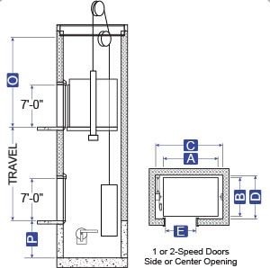
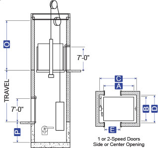
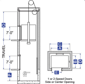
A = Platform Width
B = Platform Depth
C = Hoistway Width
D = Hoistway Depth
E = Clear Door Opening
O = Overhead
P = Pit Depth
S = Platform to Wall

Download Available Information
Contact an Elevator Package Representative to place an order
Application Summary
This design utilizes a geared machine, ropes and counterweights instead of hydraulic equipment. The main guide rails are mounted on each side of the car and an additional pair of counterweight rails are located on one side or at the rear. The geared machine, along with the related drive equipment, is generally located above the hoistway in a penthouse machine room. In some limited situations, it can be located next to the hoistway at a lower landing. This latter arrangement is referred to as a basement traction.
Advantages
- No risk of oil contamination to the ground.
- Accommodates front and rear openings in any configuration.
- Available for both low and high capacity cars.
- Nearly unlimited floor travel is possible.
- Has greater power efficiency than hydraulic applications.
- Allows significantly higher car speeds than hydraulic designs.
ENGINEERED TO ORDER – Contact MEI For Sizes or Capacities Outside Listed Ranges
Specifications
A x B
C x D
9′ -3 1/2″
9′ -2 1/2“
10′ -6″
10′ -9 1/2“
9′ -2 1/2“
10′-8 1/2“
11′ -9″
11′-8 1/2“
12′ -4 1/2″
10′ -11″
13′ -5 1/2
11′ -0 1/2“
11′-6″
12′ -2“
10′ -8 1/2“
12′ -0″
13′ -0 1/2“
10′ -7 1/2“
11′-6″
12′ -2“
10′ -8 1/2“
12′-1 1/2“
13′ -2″
10′-9″
Based on car speed of 200 fpm • Cab Height = 8′ -0″ • For seismic applications add 3″ to hoistway width and 1″ to hoistway depth
A x B
C x D
6′-8 1/4“
4′ -3 1/2“
6′-8 1/4
4′ -3 1/2“
7′-1 1/4“
4′ -8 1/2“
7′-9 1/4“
5′ -4 1/2“
7′-9 1/4“
5′ -4 1/2“
Based on car speed of 200 fpm • Cab Height = 8′ -0″ • For seismic applications add 3″ to hoistway width and 1″ to hoistway depth
A x B
C x D
5′ -9″
4′ -3 1/2“
5′ -9″
4′ -3 1/2“
6′ -2″
4′ -8 1/2“
6′ -10″
5′ -4 1/2“
7′ -9 1/2“
5′ -4 1/2“
6′ -10″
5′ -4 1/2“
7′ -8 1/2“
5′ -3 1/2“
Based on car speed of 200 fpm • Cab Height = 8′ -0″ • For seismic applications add 3″ to hoistway width and 1″ to hoistway depth
A x B
C x D
9′ -0 1/2“
10′ -4″
9′ -2 1/2″
9′ -1 1/2“
10′ -5″
9-11′ -1/2″
9′ -10 1/2“
11′ -2″
9′ -7 1/2“
10′ -5“
10′ -3 1/2“
11′ -7″
Based on car speed of 200 fpm • Cab Height = 8′ -0″ • For seismic applications add 3″ to hoistway width and 1″ to hoistway depth
Based on car speed of 200 fpm • Cab Height = 8′ -0″ • For seismic applications add 3″ to hoistway width and 1″ to hoistway depth
Based on car speed of 200 fpm • Cab Height = 8′ -0″ • For seismic applications add 3″ to hoistway width and 1″ to hoistway depth
Based on car speed of 200 fpm • Cab Height = 8′ -0″ • For seismic applications add 3″ to hoistway width and 1″ to hoistway depth
Based on car speed of 200 fpm • Cab Height = 8′ -0″ • For seismic applications add 3″ to hoistway width and 1″ to hoistway depth
*Speeds exceeding 200 FPM require additional overhead and pit depth. Minimum pit depth is based on the use of spring buffers. Add 5″ to pit depth if oil buffers are required or car speed exceeds 200 FPM.
- 225 FPM = add 6″ of overhead & 5″ of pit depth
- 250 FPM = add 7″ of overhead & 5″ of pit depth
- 300 FPM = add 8″ of overhead & 5″ of pit depth
- 350 FPM = add 10″ of overhead & 5″ of pit depth
Contact us for your next custom Gearless elevator package. MEI provides gearless cars up to 9,000 lb. capacity at 450 FPM.